Power Chuck Manufacturer
About Power Chuck
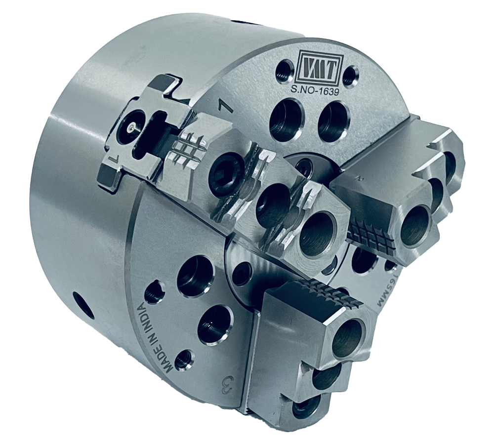
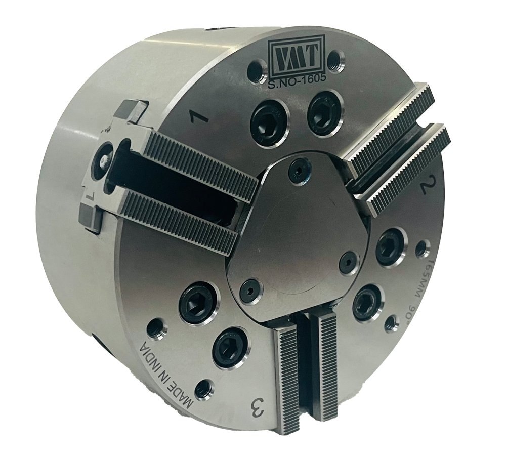
VMT power chuck rotates at high speed, Suitable for modern turning center. These power chuck have a large through bore and are suitable for bar work compact in design and less weight.
Technical Feature Equipment
- Gripping force transmission wedge hook.
- Case hardened & body assure long chuck life.
- 2 Jaw Start from dia 100 mm to 315 mm.
- 3 Jaw chuck available in all dia.
- 4 Jaw Chuck start from dia 165 mm.
Equipment are
- 2, 3 or 4 Jaw Chuck.
- 1 Set soft Jaws.
- 1 Set T-Nut with bolt.
- Mounting bolt.
- Chucknut Handle with dowel and grease gun.
Get A Quote
A Power Chuck | Hydraulic Chuck is a type of chuck used in computer numerical control (CNC) machines for securely holding and gripping workpieces during machining operations. It is an essential component in CNC turning centers and CNC milling machines.
Here's a description of a typical CNC hydraulic / Power Chuck
1. Construction: A CNC hydraulic chuck consists of a body made of high-quality steel or other suitable materials. The chuck body is precision-machined to ensure accuracy and durability. Inside the chuck body, there is a hydraulic mechanism that controls the clamping and releasing of the workpiece.
2. Hydraulic System: The hydraulic system of the chuck consists of a hydraulic cylinder, hydraulic piston, and hydraulic pressure supply. The hydraulic pressure is supplied through hydraulic lines connected to the chuck. When hydraulic pressure is applied, it activates the piston, which moves the jaws or clamping mechanism to grip the workpiece securely.
3. Jaws or Clamping Mechanism: The chuck has multiple jaws or a clamping mechanism that closes or opens based on the hydraulic pressure applied. The number of jaws can vary depending on the chuck design and application requirements. These jaws or the clamping mechanism are usually reversible and interchangeable to accommodate different workpiece sizes and shapes.
4. Actuation: The hydraulic chuck is actuated by the CNC machine's control system. The CNC program sends commands to the hydraulic chuck, controlling the clamping and releasing actions. The chuck responds to these commands by activating the hydraulic mechanism to grip or release the workpiece.
5. Accuracy and Repeatability: CNC hydraulic chucks are designed to provide high accuracy and repeatability. The hydraulic clamping mechanism ensures a strong and consistent grip on the workpiece, preventing slippage during machining operations. This accuracy and repeatability are crucial for achieving precise and consistent results in CNC machining.
6. Compatibility: CNC hydraulic chucks are available in various sizes and configurations to fit different CNC machine spindles and workpiece requirements. They can be customized and adapted to accommodate specific applications, including different chuck diameters, jaw configurations, and clamping forces.
In summary, a CNC hydraulic chuck is a robust and reliable workholding device used in CNC machining. It utilizes a hydraulic mechanism to provide secure clamping and precise positioning of workpieces, contributing to the overall accuracy and efficiency of CNC operations.
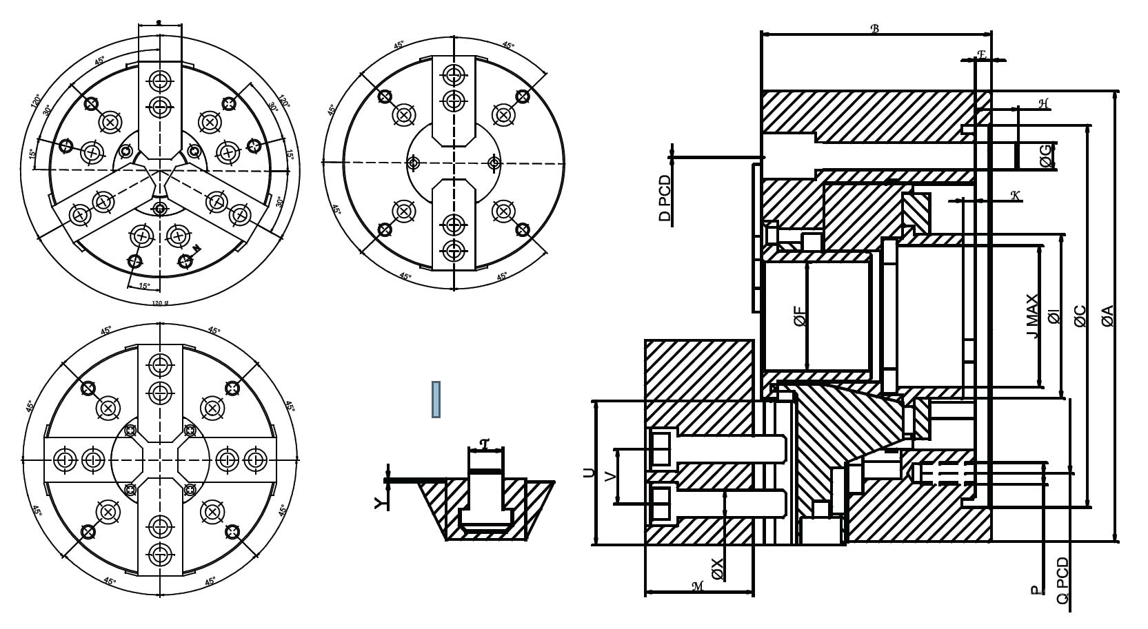
Product Drawing
| SIZE | 135 MM | 165 MM | 200 MM | 250 MM | 300 MM |
|---|---|---|---|---|---|
| THROUGH HOLE | 34 mm | 48 mm | 52 mm | 70 mm | 88 mm |
| PLUNGER STROKE | 10 mm | 15 mm | 18 mm | 20 mm | 24 mm |
| JAWS STROKE | 4.5 | 5.5 | 7.4 | 8.8 | 10.6 |
| GRIPPING RANGE | 10-128 | 32-165 | 25-200 | 28-250 | 42-300 |
| MAX. GRIPPING FORCE (Kgf) | 3500 | 5300 | 7500 | 11500 | 13000 |
| PCD | 82.6 | 104.8 | 133.4 | 171.4 | 171.4 |
| RPM | 6000 | 6000 | 5000 | 4000 | 3400 |
| WEIGHT (kg) | 6.5 | 12 | 18 | 27 | 43 |
| SIZE | 135 MM | 165 MM | 200 MM | 250 MM | 300 MM |
|---|---|---|---|---|---|
| A | 135 | 165 | 200 | 250 | 300 |
| B | 60 | 85 | 91 | 100 | 110 |
| C (H6) | 110 | 140 | 170 | 220 | 220 | 300 |
| D PCD | 82.6 | 104.8 | 133.4 | 171.4 | 171.4 | 235 |
| E | 4 | 6 | 7 | 7 | 7 |
| F | 34 | 42 | 52 | 70 | 88 |
| G | M10 x 3 | M10 x 6 | M12 x 6 | M16 x 6 | M16 x 6 M20 x 6 |
| H | 13 | 15 | 17 | 24 | 30 |
| I | 45 | 58 | 67 | 75 | 104 |
| J | M40 x 1.5 | M52 x 2 | M60 x 2 | M70 x 2 | M95 x 2 |
| K1 MAX. | 1.5 | 4 | 1 | 1 | 3.5 |
| K2 MIN. | -8.5 | 19 | 20 | 20 | 26.5 |
| M | 28 | 40 | 51 | 60 | 61 |
| N | M6 | M8 | M10 | M10 | M12 |
| O PCD | 108 | 145 | 175 | 220 | 220 |
| P | M6 | M6 | M6 | M8 | M8 |
| Q PCD | 96 | 116 | 150 | 190 | 190 |
| R | 27 | 32 | 40 | 45 | 52 |
| SERRATION | 60° | 90° | 60° | 90° | 60° | 90° | 60° | 90° | 60° | 90° |
| T | 10 | 12 | 14 | 17 | 16 | 21 | 21 |
| U | 41 | 52 | 62.5 | 75 | 87 |
| V | 14 | 16 | 25 | 19 | 30 | 25 | 30 |
| X | M8 | M10 | M12 | M12 | M16 | M16 |
| Y | 2 | 2 | 2 | 2 | 2 |